Showing posts with label to. Show all posts

Tuesday, September 10, 2013

12V to 220V 100W Transistor Inverter Circuit Diagram

 12V to 220V 100W Transistor Inverter Circuit Diagram

12V to 220V 100W Transistor Inverter

12V to 220V 100W transistor based power inverter.
Read the rest entry[...]

Tuesday, July 30, 2013

4 Bit Analogue to Digital Converter

The operation of the converter is based on the weighted adding and transferring of the analogue input levels and the digital output levels. It consists of comparators and resistors. In theory, the number of bits is unlimited, but each bit needs a comparator and several coupling resistors. The diagram shows a 4-bit version. The value of the resistors must meet the following criteria:
  • R1:R2 = 1:2;
  • R3:R4:R5 = 1:2:4;
  • R6:R7:R8:R9 = 1:2:4:8.
The linearity of the converter depends on the degree of precision of the value of the resistors with respect to the resolution of the converter, and on the accuracy of the threshold voltage of the comparators. This threshold level must be equal, or nearly so, to half the supply voltage. Moreover, the comparators must have as low an output resistance as possible and as high an input resistance with respect to the load resistors as feasible. Any deviation from these requirements affects the linearity of the converter adversely.
Circuit diagram:
4-bit_AnalogueTo_Digital_Converter-Circuit-Diagramw
4-Bit Analogue to Digital Converter Circuit Diagram
If the value of the resistors is not too low, the use of inverters with an FET (field-effect transistor) input leads to a near-ideal situation. In the present converter, complementary metal-oxide semiconductor (CMOS) inverters are used, which, in spite of their low gain, give a reasonably good performance. If standard comparators are used, take into account the output voltage range and make sure that the potential at their non-inverting inputs is set to half the supply voltage. If high accuracy is a must, comparators Type TLC3074 or similar should be used. This type has a totem-pole output. The non-inverting inputs should be interlinked and connected to the tap of a a divider consisting of two 10 kΩ resistors across the supply lines. It is essential that the converter is driven by a low-resistance source. If necessary, this can be arranged via a suitable op amp input buffer. The converter draws a current not exceeding 5 mA.
Source :www.extremecircuits.net
Read the rest entry[...]

Thursday, July 11, 2013

Variable 5 to 20V DC Supply Rise

If you are looking for a low drop voltage regulator that can provide a power supply of 1A with an output voltage of between 5V and 20V DC, National Semiconductor LM2941 Low Dropout Adjustable Regulator is that you can pick to make use of. Its a typical dropout voltage of 0.5V which means that the input supply need only must be 0.5V DC over the desired output voltage. Its other features include internal short circuit current limit and reverse battery protection.

As shown in the schematic below, the regulator has five pins which consists of the ON/OFF control, Input Voltage, Output Voltage, Ground & Adjustable pins. ON/OFF is used for the purpose of switching on & off of the regulator. The capacitors C1 & E1 are to be placed as close as feasible to the regulator.


The output of the circuit can be varied by varying the worth of potentiometer VR1 from 5V DC to 20V DC. The input voltage is limited from five.5V DC to 30V DC. Resistor R1 must be greater than 1K. The worth of the VR1 that needs to be set is calculated from the formula given below:

VR1 = R1[(Vout/1.275) - 1] ohm

If R1=1K, Vout = 5V, VR1 should be set to 2.9K ohm.

If R1=1K, Vout = 20V, VR1 should be set to 14.7K ohm

Read the rest entry[...]

Wednesday, July 10, 2013

Build a 500W Low Cost 12V to 220V Inverter

Attention: This Circuit is using high voltage that is lethal. Please take appropriate precautions

Using this circuit you can convert the 12V dc in to the 220V Ac. In this circuit 4047 is use to generate the square wave of 50hz and amplify the current and then amplify the voltage by using the step transformer.

How to calculate transformer rating

The basic formula is P=VI and between input output of the transformer we have Power input = Power output

For example if we want a 220W output at 220V then we need 1A at the output. Then at the input we must have at least 18.3V at 12V because: 12V*18.3 = 220v*1
So you have to wind the step up transformer 12v to 220v but input winding must be capable to bear 20A.

500W Low Cost 12V to 220V Inverter Circuit
Read the rest entry[...]

Monday, July 8, 2013

230 Volt AC To Inverter Switching Circuit Diagram

Description

                  Before three weeks i am introduced  inverter circuit diagram but the circuit not included ac to inverter switching part so today i introducing a 230 Volt Ac to inverer switching circuit diagram .

Circuit showing a inverter switching  . Here i have used  bc 558 ,BC 548 and a relay for making this circuit . 230 volt connected to the base of the transistor Q1.When the power is ON positive volt coming to the base of the transistor so the relay circuit is open and load working in 230 V AC .When the power is OFF ground voltage coming to the base of the transistor so the Base of the Q2 is positive there for the   relay circuit closed and load working in inverter input .Part list and applications are showing below.


Part List


Component No: Value  Usage
R1 100KΩ Emitter Load
R2 10K Ω Base Biasing 
R3180KΩ  Current Limiting 
Q1BC558  Switching  
Q2BC548   Switching 
D1 IN4007   Relay Balancing 
RL112 V  Inverter Switching 


Applications


Inverter Switching 


* AC Switching
Read the rest entry[...]

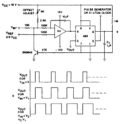
Voltage to pulse Duration Converter Circuit Diagram

This is a circuit of Voltage-to-Pulse Duration Converter. This circuit is used to convert voltage into pulse duration by combining a timer IC and an OP Amp. Accuracies to better than 1% can be obtained with this circuit (a), and the output signals (b) still retain the original frequency, independent of the input voltage. 

Voltage-to-pulse Duration Converter Circuit Diagram
 
Read the rest entry[...]

Wednesday, April 3, 2013

Simple Automatic Street Light System

The left hand side transistor T1 is rigged as a voltage comparator using a resistive network. The resistor at the upper arm is the LDR and the lower arm resistor is the preset which is used to set the threshold values or levels.  T2 is arranged as an inverter, and inverts the response received from T1.


Initially, assuming the light level is less, the LDR sustains a high resistance level across it, which does not allow enough current to reach the base of the transistor T1. This allows the potential level at the collector to saturate T2 and consequently the relay remains activated in this condition.

When the light level increases and becomes sufficiently large on the LDR, its resistance level falls, this allows more current to pass through it which eventually reaches the base of T1.

The transistor T1 conducts, pulling its collector potential to ground. This inhibits the conduction of the transistor T2, switching OFF its collector load relay and the connected lamp.

The power supply is a standard transformer, bridge, capacitor network, which supplies a clean DC to the circuit for executing the proposed actions.

The whole circuit can be built over a small piece of vero board and the entire assembly along with the power supply may be housed inside a sturdy little plastic box.

 The LDR must be placed outside the box, meaning its sensing surface should be exposed toward the ambient area from where the light level is required to be sensed.

Care should be taken that the light from the lamps does not in any way reach the LDR, which may result in false switching and oscillations.

Parts List

R1, R2, R3 = 2K2,
VR1 = 10K preset,
C1 = 100uF/25V,
C2 = 10uF/25V,
D1 ---- D6 = 1N4007
T1, T2 = BC547,
Relay = 12 volt, 400 Ohm, SPDT,
LDR = any type with 10K to 47K resistance at ambient light.
Transformer = 0-12V, 200m
Read the rest entry[...]

Monday, April 1, 2013

Serial To Parallel Converter

This converter may help if just the serial port on a personal computer is free, whereas the printer needs a parallel (Centronics) port. It converts a serial 2400 baud signal into a parallel signal. The TxD line, pin 3, CTS line, pin 8 and the DSR line, pin 6, of the serial port are used - see diagram. The CTS and DSR signals enable handshaking to be implemented. Since the computer needs real RS232 levels, an adaptation from TTL to RS232 is provided in the converter by a MAX232. This is an integrated level converter that transforms the single +5V supply into a symmetrical ±12V on.

Serial-to-Parallel Converter Circuit Diagramw

The serial-to-parallel conversion is effected by IC1. This is essentially a programmed PIC controller that produces a Centronics compatible signal from a 2400 baud serial signal (eight data bits, no parity, one stop bit). The IC also generates the requisite control signals. If there is a delay on the Centronics port, the RS232 bitstream from the computer may be stopped via the Flow signal (pin 17). This ensures that no data is lost. The controller needs a 4 MHz ceramic resonator, X1.

Source : www.extremecircuits.net

Read the rest entry[...]

Sunday, March 31, 2013

How to Calculate and Deduce Current Voltage Parameters in Transformerless Power Supplies

After carefully studying the relevant patterns, I devised a simple and effective way of solving the above issues, especially when the power supply used is a transformerless one or incorporates PPC capacitors or reactance for controlling current.

Typically, a transformerless power supply will produce an output with very low values but with voltages equal to the applied AC mains (until it’s loaded).

For example, a 1 µF, 400 V (breakdown voltage) when connected to a 220 V mains supply will produce a maximum of 70 mA of current and an initial voltage reading of 220 Volts.

However this voltage will show a very linear drop as the output gets loaded and current is drawn from the “70 mA” reservoir.

In case the load consumes the whole 70 mA would mean the voltage dropping to almost zero.
Now since this drop is linear, we can simply divide the initial output voltage with the max current to find the voltage drops that would occur for different magnitudes of load currents.

Therefore dividing 220 volts by 70 mA gives 3.14. This is the rate at which the voltage will drop for every 1 mA of current added with the load.

That means if the load consumes 20 mA of current, the drop in voltage will be 20 × 3.14 = 62.8 volts, so the output now will show a voltage of 220 – 62.8 = 157.2 volts (see figure).

However the voltage across the LED terminals will show a voltage equal to forward voltage drop of the particular LED, because the above concept again becomes applicable for the section which comes after the resistor and across the LED.

Here, the resistor further controls the current and by dividing 157 by 4700 we get 0.033 or a max of 33 mA of current and a voltage of 157, which drops linearly, so dividing 157 by 33 gives 4.75, which is the rate of voltage drop for each mA rise in the load current. The connected LED draws probably the whole 33 mA, which deducts around 33 × 4.75 = 156.75 Volts from the resistor’s output 157 Volts.

 That leaves the volts across the LED to the relevant values of around a couple volts or to be precise, the forward voltage drop of the particular type of LED.

Conclusion: From the above discussion and analysis, it becomes clear that voltage in any power supply unit is immaterial if the current delivering capability of the power supply is "relatively" low.

 For example if we consider an LED, it can withstand 30 to 40 mA current at voltages close to its "forward voltage drop", however at higher voltages this current can become dangerous for the LED, so its all about keeping the maximum current equal to the maximum safe tolerable limit of the load.

While calculating series resistor values with LEDs, instead of using the standard LED formula directly, we can use the above rule first.

That means either we choose a capacitor whose reactance value only allows the maximum tolerable current to the LED, in which case a resistor can be totally avoided.

 If the capacitor value is large with higher current outputs, then probably as discussed above we can incorporate a resistor to reduce the current to tolerable limits.

Example: In the shown diagram, the value of the capacitor produces 70 mA of max. current which is quite high for any LED to withstand. Using the standard LED/resistor formula:

R = (supply voltage VS – LED forward voltage VF) / LED current IL,
= (220 - 1.5)/0.02 = 11K,
Therefore the value of the resistor for controlling one red LED safely would be 11K.
The above theory has been assumed and deduced by me, I am not very sure about its feasibility, though

Read the rest entry[...]

How to repair nokia 6610 no ringer

Repair nokia 6610, no ringtone problem
1. Check and clean buzzer / ringer connector
2. Check buzzer / ringer, replace buzzer if needed
3. If the problem not solved, check L152 and L151, resolder and replace if needed
4. If the problem not solved, check C164, resolder and replace if needed
5. If the problem not solved, check R161, R162, resolder and replac if needed
6. If the problem still not solved, check ringer IC / N150
7. If the problem still not solved probably UEM fail/broken, resolder and replace UEM if needed
8. If the problem not solved, circuit broken trace circuit , make jumper or swap engine


Read the rest entry[...]

Wednesday, March 27, 2013

6 to 15V DC to DC Converter

A very efficient 6V to 15V DC to DC converter using LM2585 is shown here. LM2585 is a monolithic integrated voltage converter IC that can be used in various applications like flyback converters, boost converters, forward converters, multiple output converters etc. The circuit requires minimum number of external components and the IC can source up to 3A output current.
Circuit diagram :
dc-to-dc-converter-Circuit Diagram
6 to 15V DC to DC Converter Circuit Diagram

Here the IC is wired as a boost converter where resistors R1 and R2 are used to set the output voltage .The junction of R1 and R2 is connected to the feedback pin of IC1. Capacitor C4 is the input filter while capacitor C1 the filter for output. Network comprising of resistor R1 and capacitor C2 is meant for frequency compensation. Inductor L1 stores the energy for acquiring boost conversion.
Notes:    
  • Assemble the circuit on a good quality PCB.
  • LM2585 requires a heatsink.
  • Output voltage is according to the equation Vout =( (R1/R2)+1) x 1.23.
  • Capacitors other than C4 and C1 are ceramic capacitors.
  • Maximum output current LM2585 can source is 3A. 

Source : Circuitstoday
Read the rest entry[...]