Tuesday, April 30, 2013

Electric Guitar Violin Preamplifier

Magnetic pick-ups in musical instruments have a relatively high output impedance. This can result in a reduction in treble response when connected via a long cable run or to equipment with a low input impedance. This preamplifier provides a high input impedance and a low impedance output, solving both issues. It has adjustable voltage gain and can run off a battery or DC plugpack. The input signal is AC-coupled to the non-inverting input of IC1a, part of a TL074 quad op amp. This has JFET input transistors and the input impedance is set by a 330kΩ bias resistor which also sets the DC level at this input to half supply (Vcc/2). This is generated by a voltage divider comprising two 10kΩ resistors and bypassed by a 47µF capacitor to reject noise and hum.

Electric Guitar Violin Preamplifier
IC1a is configured as a non-inverting amplifier with a gain of between 2 and 20, depending on the setting of VR1. IC1a’s output is fed to VR2 via a 22µF capacitor, allowing the output volume to be set. The audio then passes to the non-inverting inputs of the remaining three op amps (IC1b-IC1d) which are connected in parallel to provide a low output impedance; it will drive a load impedance as low as 600Ω. The 100Ω resistors in series with the outputs provide short-circuit protection for the op amps and also prevent large currents from flowing between the outputs in case they have slightly different offset voltages.

The buffered signal is then AC-coupled to two output connectors using 47µF electrolytic capacitors. For Output 1, a 47kΩ resistor sets the output DC level to ground and a 220Ω series resistor provides further short-circuit protection. Output 2 is similar but includes another potentiometer (VR3) to allow its level to be set individually. Note that this means the impedance of Output 2 can be high (up to 2.5kΩ depending on the position of VR3’s wiper). The total harmonic distortion of this circuit is typically less than 0.01% with the gain set to six. If a TL064 is used instead of a TL074, the current drain will decrease but there will be more noise at the output. Finally, the input imped

Read the rest entry[...]

Friday, April 26, 2013

Arduino Based Capacitive Touch Screen

Arduino based projects are quite complicated and is no cake walk for beginners in this field. Interfacing a tablet with the microcontroller is a daunting task. Let see how its done here.


Hacks and Mods: Arduino Based Capacitive Touch Screen
 
The primary focus should be on using the appropriate drivers for the tablet. This makes it a USB host. As seen in the video, light can be a medium of communication between the tablet and the microcontroller. A photo diode or photoresistor is what is needed here and this should be pressed against the screen.

Building a touch sensing capability can help in providing communication between the microcontroller and the tablet. Capacitive touch screens function by sensing the capacitance changes on the screen. In this case, a large conductive brass plate is used to simulate touch. The surface area of the conductor used here to simulate the touch sould be large.

Testing can be done by touching the scrren with a wire and holding the other end. This may not work. This is made to work by sticking a piece of aluminum foil on to the screen and connecting the free end to the pin that is available on the arduino. The video shows the working of the capacitive touch screen. The setup is quite fragile and a little more circuitry could improve its reliability. Thus the capacitive touch screen is done.
Read the rest entry[...]

Sunday, April 21, 2013

SP Semi Automatic Paintbrush

Got a replacement InkShield and progressing to build an Open hardware project? Then why not strive creating the Semi-Automatic Paintbrush. browse on to grasp a lot of concerning this.


Any work of art are often copied using this and therefore the elements that are needed to form this is often listed below:
IR camera
InkShield
Ink cartridge
IR LED.

The software thats run on a desktop for this purpose is understood as paintbrush.py. The software plays the role of mapping the camera focus with the co-ordinate system of the canvas. Four LEDs are placed at every corner of the canvas and therefore the mapping is calibrated by hitting a key when needed.

The region of the image is captured by tracking the motion of the LEDs. the mandatory commands are send to an Arduino with the InkShield by means that of a script written for this purpose. The script tells the arduino that nozzle to fireplace and additionally the grey level that must be achieved by the firing nozzle. so as to avoid flooding, the painted areas are tracked.

Thats all its. The paintbrush is complete. this is often a lot of of a fun-based project and may be tired some spare time using the elements mentioned earlier. the desired script is out there on github. The InkShield library employed by the
Read the rest entry[...]

SP Network Voltage Indicator

Using this schematic is created a network voltage indicator electronic circuit. If the input voltage is gift across the network, the optocoupler transistor is open, T1 is blocked and controlled rectifier, Th1, is in a very state of conduction. Since each terminals of the piezoelectric buzzer is at identical potential, buzzer is off. If voltage disappears, the transistor T1 enters the conduction and therefore makes the terminal of buzzer to be placed on the bottom (maintains thyristor conduction state).


during this state of affairs, theres a sufficiently giant potential distinction across the buzzer and D5s to see that these 2 components to point AC power loss, each audible and visual. By pressing the reset button current is interrupted by Th1, therefore thyristor enter in blocking state and therefore the different terminal of the buzzer is connected to ground.
Read the rest entry[...]

Saturday, April 13, 2013

Sensitive Audio Power Meter

As a follow-up to the straightforward audio energy  meter described in [1], the author has developed a more delicate model. In follow,  you  rarely  use  more  than  1 watt  of  audio  energy in a standard living-room surroundings.  The best time the basic public use extra is at a  celebration when they want to exhibit how loud their  stereo gadget is, through which case peaks of more  than 10 W will no longer be wonderful. With this circuit, the twin LED starts to gentle up  green at round 0.1 watt into 8 ohms (0.2 watt  into 4 ohms). Naturally, this is decided by the  specific form of LED that's used.
 
Circuit diagram:

Sensitive Audio Power Meter Circuit Diagram
 
Here it is  essential to make use of a low current kind. The capacitor is first charged by implys of D1 after which discharged by means of the fairway LED. This voltage-doubler effect  increases the sensitivity of the circuit. Above a level of 1 watt, the transistor limits the current in the path of the green LED and the crimson LED con ducts enough to provide an orange hue.The pink colour predominates above 5 watts. Of route, that you can additionally use two separate ‘normal’ LEDs. However, this arrangement can't generate an orange hue. For any testing that could be necessary, you must use  generator with a DC-coupled output. If there is a capacitor in the output path, it may presumably lead to misleading consequences. 
 
Reference: Simple Audio Power Meter, Elektor July & August 2008.

Author : Michiel Ter Burg Streampowers
Read the rest entry[...]

Installtrailer Light Taillight Converter Towing

Trailer Wiring on Looking To The Rear For The Trailer Plug   The Pins Are Reversed   And
Looking To The Rear For The Trailer Plug The Pins Are Reversed And.


Trailer Wiring on Trailer Wiring Diagram Light Plug Brakes Hitch 4 Pin Way Wire Brake
Trailer Wiring Diagram Light Plug Brakes Hitch 4 Pin Way Wire Brake.


Trailer Wiring on Trailer Light Wiring   Typical Trailer Light Wiring Diagram
Trailer Light Wiring Typical Trailer Light Wiring Diagram.


Trailer Wiring on Trailer Parts Depot   Trailer Wiring Kits   Trailer Parts
Trailer Parts Depot Trailer Wiring Kits Trailer Parts.
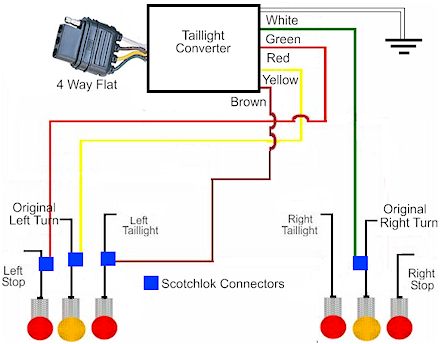

Trailer Wiring on How To Install A Trailer Light Taillight Converter In Your Towing
How To Install A Trailer Light Taillight Converter In Your Towing.
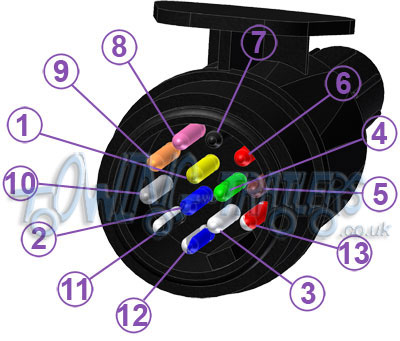

Trailer Wiring on Wiring For 13 Pin Euro Plugs   Sockets For Trailers   Caravans   Uk
Wiring For 13 Pin Euro Plugs Sockets For Trailers Caravans Uk.


Trailer Wiring on Trailer Wiring Diagram
Trailer Wiring Diagram.


Trailer Wiring on Wiring Color For 7 Pin Trailer Plug Jpg
Wiring Color For 7 Pin Trailer Plug Jpg.
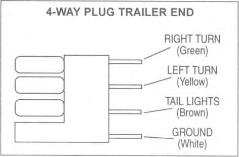

Trailer Wiring on Trailer Wiring Diagrams  Johnson Trailer Sales  Colfax Wisconsin
Trailer Wiring Diagrams Johnson Trailer Sales Colfax Wisconsin.


Trailer Wiring on 12s Wiring Diagram
12s Wiring Diagram.


Read the rest entry[...]

Friday, April 12, 2013

Luggage Protector Circuit Using 555 Timer IC

The circuit is called protector alarm circuit to protect from the theft of your luggage or bags. This circuit is built electronically using 555 timer
IC. The alarm will rise highly when the thin wire is cut off by the
thief.  The circuit configuration using 555 timer IC acts as a astable multivibrator which produce signal tone of frequency of about 1 KHz and produce sound like a shrill noise away the output speaker.

If you need to know 555 Timer configuration click here and download
IC’s
5number pin is directly connected to the power supply. 10k, 68k
resistor and 0.01uf capacitor are connected to generate specific range of frequency
like as 1KHz. You can change output frequency by changing the value of
 resistor and capacitor.  Pin 1 is directly connected to the ground.
Output is taken from pin 3. A 8Ohms speaker is connected to the output
for alarm sound. Thin wire is connected as shown in figure.
The
wire would be very thin copper like 36 SWG or higher. You can use one
gage of normal wire. The driving voltage of the circuit is 5 Volt to 12
Volt.
Read the rest entry[...]

Subwoofer Wiring Diagrams Dual Voice Coilspeaker

Subwoofer Wiring on Subwoofer Wiring Diagrams  Four 4 Ohm Dual Voice Coil  Dvc  Speakers
Subwoofer Wiring Diagrams Four 4 Ohm Dual Voice Coil Dvc Speakers.
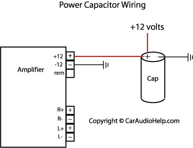

Subwoofer Wiring on Car Audio Capacitor Installation
Car Audio Capacitor Installation.


Subwoofer Wiring on Wiring Diagram 2001 Honda Civic Stereo Wiring Diagram Related Posts
Wiring Diagram 2001 Honda Civic Stereo Wiring Diagram Related Posts.


Subwoofer Wiring on Car Stereo Head Unit Wiring Harness
Car Stereo Head Unit Wiring Harness.


Subwoofer Wiring on Subwoofer Wiring Diagrams  One 2 Ohm Dual Voice Coil  Dvc  Speaker
Subwoofer Wiring Diagrams One 2 Ohm Dual Voice Coil Dvc Speaker.


Subwoofer Wiring on Dual Voice Coil Wiring Driver By Stereo Integrity   Circuit Schematic
Dual Voice Coil Wiring Driver By Stereo Integrity Circuit Schematic.


Subwoofer Wiring on Mr2 Subwoofer   Enclosure Combo Mr2 Subwoofer   Enclosure Combo
Mr2 Subwoofer Enclosure Combo Mr2 Subwoofer Enclosure Combo.
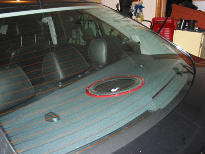

Subwoofer Wiring on Subwoofer Installation Details
Subwoofer Installation Details.


Subwoofer Wiring on Infinity  Subwoofer Box    Kenwood  Class D Amplifier    Wiring Kit
Infinity Subwoofer Box Kenwood Class D Amplifier Wiring Kit.


Subwoofer Wiring on Kfc W112s   Kac 6104   Box   Amp Kit Kenwood 12  800 Watt Subwoofer
Kfc W112s Kac 6104 Box Amp Kit Kenwood 12 800 Watt Subwoofer.


Read the rest entry[...]

Mobile Incoming Call Indicator Circuit Diagram

This circuit can be used to escape from the nuisance of mobile phone rings
when you are at home. This circuit will give a visual indication if
placed near a mobile phone even if the ringer is deactivated.


When
a call is coming to the mobile phone, the transmitter inside it becomes
activated. The  frequency of the transmitter is around 900MHz.The 
coil L1 picks up these oscillations by induction and feds it to the
base of Q1. This makes the transistor Q1 activated.Since the Collector
of Q1 is connected to the pin 2 of IC1 (NE555) , the IC1 is triggered to make the LED connected at  its output pin (pin 3) to blink. The blinking of the LED is the indication of incoming call.
Notes:
  •   
    The coil L1 can be made by making 150 turns of 36 SWG enameled copper
    wire on a 5mm dia   plastic former.Or you can purchase a 10 uH coil from
    shop if available.
  •     The circuit can be powered from a 6V battery.
  •     Assemble the circuit on a good quality PCB.
  •     C1 & C3 are to be polyester  capacitors.
  •     The electrolytic capacitor C2 must be rated 10V.

Read the rest entry[...]

Hoppy Vehicle Wiring 11140475 Hoppy Vehicle Wiring 43315

Vehicle Wiring Products on Car Alarm Wire Harness Auto 2003  Oem Number Auto 2003   Dongguan
Car Alarm Wire Harness Auto 2003 Oem Number Auto 2003 Dongguan.


Vehicle Wiring Products on Automotive Wiring Harness Automotive Wiring Harness For Seating
Automotive Wiring Harness Automotive Wiring Harness For Seating.


Vehicle Wiring Products on Hoppy Vehicle Wiring Kit   11140475 Hoppy Vehicle Wiring Kit   43315
Hoppy Vehicle Wiring Kit 11140475 Hoppy Vehicle Wiring Kit 43315.
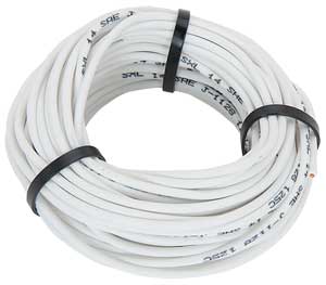

Vehicle Wiring Products on Jegs Performance Products 10857   Jegs Premium Automotive Wire
Jegs Performance Products 10857 Jegs Premium Automotive Wire.


Vehicle Wiring Products on Automotive Wiring Harness 2
Automotive Wiring Harness 2.


Vehicle Wiring Products on Of 1995   1996 Ford Windstar Into Car Wire Harness  Part Cf Whfd2
Of 1995 1996 Ford Windstar Into Car Wire Harness Part Cf Whfd2.


Vehicle Wiring Products on Jegs Performance Products 10806   Jegs Premium Automotive Wire
Jegs Performance Products 10806 Jegs Premium Automotive Wire.


Vehicle Wiring Products on Ignition Wire Boots  China Manufacturer    Car Parts   Components
Ignition Wire Boots China Manufacturer Car Parts Components.


Vehicle Wiring Products on Http   Www Vehicle Wiring Products E   Oto 192175 Jpg
Http Www Vehicle Wiring Products E Oto 192175 Jpg.


Vehicle Wiring Products on Automotive Innovation Inc  Automotive Innovation Inc Manufacturers In
Automotive Innovation Inc Automotive Innovation Inc Manufacturers In.


Read the rest entry[...]

Thursday, April 11, 2013

Moduler Audio Preamplifier

High Quality, Discrete Components Design, Input and Tone Control Modules
To complement the 60 Watt MosFet Audio Amplifier a High Quality Preamplifier design was necessary. A discrete components topology, using + and - 24V supply rails was chosen, keeping the transistor count to the minimum, but still allowing low noise, very low distortion and high input overload margin. Obviously, the modules forming this preamplifier can be used in different combinations and drive different power amplifiers, provided the following stages present a reasonably high input impedance (i.e. higher than 10KOhm).

Main Module:
If a Tone Control facility is not needed, the Preamplifier will be formed by the Main Module only. Its input will be connected to some sort of changeover switch, in order to allow several audio reproduction devices to be connected, e.g. CD player, Tuner, Tape Recorder, iPod, MiniDisc etc. The total amount and type of inputs is left to the choice of the home constructor. The output of the Main Module will be connected to a 22K Log. potentiometer (dual gang if a stereo preamp was planned). The central and ground leads of this potentiometer must be connected to the power amplifier input.

Main Module Circuit diagram:
Main Module Circuit Diagram
Parts:
R1_____________1K5 1/4W Resistor
R2_____________220K 1/4W Resistor
R3_____________18K 1/4W Resistor
R4_____________330R 1/4W Resistor
R5_____________39K 1/4W Resistor
R6_____________56R 1/4W Resistor
R7,R10_________10K 1/4W Resistors
R8_____________33K 1/4W Resistor
R9_____________150R 1/4W Resistor
R11____________ 6K8 1/4W Resistor
R12,R13________100R 1/4W Resistors
R14____________100K 1/4W Resistor
C1_____________220nF 63V Polyester Capacitor
C2_____________220pF 63V Polystyrene or ceramic Capacitor
C3_____________1nF 63V Polyester or ceramic Capacitor
C4,C7__________47µF 50V Electrolytic Capacitors
C5,C6__________100µF 50V Electrolytic Capacitors
Q1,Q2__________BC550C 45V 100mA Low noise High gain NPN Transistors
Q3_____________BC556 65V 100mA PNP Transistor
Q4_____________BC546 65V 100mA NPN Transistor

Tone Control Module:

This Module employs an unusual topology, still maintaining the basic op-amp circuitry of the Main Module with a few changes in resistor values. A special feature of this circuit is the use of six ways switches instead of the more common potentiometers: in this way, precise "tone flat" setting, or preset dB steps in bass and treble boost or cut can be obtained. Tone Control switches also allow a more precise channel matching when a stereo configuration is used, avoiding the frequent poor alignment accuracy presented by common ganged potentiometers. Six ways (two poles for stereo) rotary switches were chosen for this purpose as easily available. This dictated the unusual "asymmetrical" configuration of three positions for boost, one for flat and two for cut.
This choice was based on the fact that tone controls are used in practice more for frequency boosting than for cutting purposes. In any case, +5dB +10dB and +15dB of bass boost and -3dB and -10dB of bass cut were provided. Treble boost was also set to +5dB +10dB and +15dB and treble cut to -3.5dB and -9dB. Those wishing to use common potentiometers in the usual way for Tone Controls may use the circuit shown enclosed in the dashed box (bottom-right of the Tone Control Module circuit diagram) to replace switched controls. The Tone Control Module should usually be placed after the Main Input Module, and the volume control inserted between the Tone Control Module output and the power amplifier input. Alternatively, the volume control can also be placed between Main Input Module and Tone Control Module, at will. Furthermore, the position of these two modules can be also interchanged.

Tone Control Module Circuit diagram:

Tone Control Module Circuit Diagram

Parts:
R1,R7___________47K 1/4W Resistors
R2_____________220K 1/4W Resistor
R3______________18K 1/4W Resistor
R4_____________330R 1/4W Resistor
R5______________39K 1/4W Resistor
R6______________56R 1/4W Resistor
R8_____________150R 1/4W Resistor
R9______________10K 1/4W Resistor
R10,R16__________6K8 1/4W Resistors
R11,R12________100R 1/4W Resistors
R13____________100K 1/4W Resistor
R14______________1K5 1/4W Resistor
R15,R21,R22______4K7 1/4W Resistors
R17,R24,R26______8K2 1/4W Resistors
R18______________3K3 1/4W Resistor
R19______________1K 1/4W Resistor
R20____________470R 1/4W Resistor
R23,R25_________12K 1/4W Resistors
R27,R28__________4K7 1/4W Resistors
C1_____________220nF 63V Polyester Capacitor
C2_______________1nF 63V Polyester or ceramic Capacitor
C3,C6___________47µF 50V Electrolytic Capacitors
C4,C5__________100µF 50V Electrolytic Capacitors
C7______________10nF 63V Polyester Capacitor
C8,C9__________100nF 63V Polyester Capacitors
Q1,Q2_________BC550C 45V 100mA Low noise High gain NPN Transistors
Q3____________BC556 65V 100mA PNP Transistor
Q4____________BC546 65V 100mA NPN Transistor
SW1,SW2_______2 poles 6 ways Rotary Switches
Simpler, alternative Tone Control parts:
P1______________22K Linear Potentiometer
P2______________47K Linear Potentiometer
R29,R30________470R 1/4W Resistors
R31,R32__________4K7 1/4W Resistors
C10_____________10nF 63V Polyester Capacitor
C11,C12________100nF 63V Polyester Capacitors

Power supply:
The preamplifier must be feed by a dual-rail, +24 and -24V 50mA dc power supply. This is easily achieved by using a 48V 3VA center-tapped mains transformer, a 100V 1A bridge rectifier and a couple of 2200µF 50V smoothing capacitors. To these components two 24V IC regulators must be added: a 7824 (or 78L24) for the positive rail and a 7924 (or 79L24) for the negative one. The diagram of such a power supply is the same of that used in the Headphone Amplifier, but the voltages of the secondary winding of the transformer, smoothing capacitors and IC regulators must be uprated. Alternatively, the dc voltage can be directly derived from the dc supply rails of the power amplifier, provided that both 24V regulators are added.

Note:
If this preamplifier is used as a separate, stand-alone device, thus requiring a cable connection to the power amplifier, some kind of output short-circuit protection is needed, due to possible shorts caused by incorrect plugging. The simplest solution is to wire a 3K3 1/4W resistor in series to the output capacitor of the last module (i.e. the module having its output connected to the preamp main output socket).

Technical data:

Main Module Input sensitivity:
250mV RMS for 1V RMS output
Tone Control Module Input sensitivity:
1V RMS for 1V RMS output
Maximum output voltage:
13.4V RMS into 100K load, 11.3V RMS into 22K load, 8.8V RMS into 10K load
Frequency response:
flat from 20Hz to 20KHz
Total harmonic distortion @ 1KHz:
1V RMS 0.002% 5V RMS 0.003% 7V RMS 0.003%
Total harmonic distortion @10KHz:
1V RMS 0.003% 5V RMS 0.008% 7V RMS 0.01%

Source :http://www.ecircuitslab.com/2011/06/moduler-audio-preamplifier.html  
Read the rest entry[...]

Simple Smoggy

Even if your good old (Sony) Walkman  sees little use nowadays it would be a  shame to get rid of it altogether. The more  so when just removing the tape head  would allow the built-in audio amplifier  to become an outstanding electrosmog  detector for a variety of purposes. Looking at the schematic, readers with RF  experience will have no difficulty in recognising the diodes and coils of the two  detector-receivers, which serve to capture and demodulate RF signals. With its  coil of four turns (L2) one receiver covers the higher frequency range of the  electromagnetic waves, whilst the sec-ond detector takes care of the lower frequency range.

Simple Smoggy Circuit diagram:
Simple Smoggy-Circuit Schematic

For this reason a coil with a  greater number of turns is required: L1 is  an RF choke of about 250 µH. The precise  value is not critical and it could equally be  220 µH or 330 µH. The outputs of both detector-receivers  are connected to the cables disconnected  previously from the tape heads, feeding the  right and left channel inputs to the Walk-man’s audio amplifier. Please note here that  the screening of the tape head cable does not  have to be absolutely identical to the ground connection of the amplifier circuitry. As  we are dealing with a stereo amplifier,  we are listening into both channels and  thus both RF ranges at the same time.

One channel of the amplifier can also be  used to demodulate low-frequency magnetic alternating fields  via a capacitor  (C3) bypassing diode D1 and connecting either a third coil (L3, for instance;  a telephone recording adapter) as the  pickup device or else a long piece of wire  for acquiring low frequency AC electrical fields. Sources like this are discernible mainly by a distinct 50 Hz (or 60 Hz)  humming in the earphones. Predicting what you may hear down to  the very last detail is difficult, since every  locality has its own, individual interference sources. Nevertheless, with practice  users will succeed in identifying these  interference sources by their particular  audio characteristics.

To sum up, four different ‘sensors’ can be  connected to the inputs of this circuit:  ANT1 (approx. 50 cm long whip antenna),  ANT2 (3.5 cm short stub antenna), ANT3  (approx. 1 m long wire antenna for low frequency electrical fields) and a coil for magnetic fields. Finally, two more tips:
  1. Use only ‘good old’ germanium diodes for  D1 and D2. Sensitivity will be much reduced if  silicon diodes are used, as these have a higher  threshold voltage.
  2. Smoggy does not provide an absolute indi-cation of field strength and even more so can-not provide any guidance whether anything  it detects might be harmful. Its function is to detect electromagnetic signals and compare  their relative magnitude.
Author : Tony Ruepp  - Copyright : Elektor

Source :  http://www.ecircuitslab.com/2012/05/simple-smoggy-circuit-schematic.html
Read the rest entry[...]

Constructing your own Dual Power Supply Rise

Many times the hobbyist desires to have a simple, dual power supply for a project. Existing power supplies may be large either in power output or physical size. a simple Dual Power Supply is necessary.For most non-critical applications the best & simplest choice for a voltage regulator is the 3-terminal type.The three terminals are input, ground & output.

The 78xx & 79xx series can provide up to 1A load current & it have on chip circuitry to prevent damage in the event of over heating or excessive current. That is, the chip basically shuts down than blowing out. These regulators are cheap, simple to make use of, & they make it practical to design a method with plenty of P C Bs in which an unregulated supply is brought in & regulation is done locally on each circuit board.

This Dual Power Supply project provides a dual power supply. With the appropriate choice of transformer & 3-terminal voltage regulator pairs you can basically build a tiny power supply delivering up to amp at +/- 5V, +/- 9V, +/- 12V, +/-15V or +/-18V. You require to provide the middle tapped transformer and the 3-terminal pair of regulators you require:7805 & 7905, 7809 & 7909, 7812 & 7912, 7815 & 7915or 7818 & 7918.

The user must pick the pair they needs for his particular application.

Note that the + & - regulators do not must be matched: you can for example, use a +5v & -9V pair. However,the positive regulator must be a 78xx regulator, & the negative a 79xx. They have built in plenty of safety in to this project so it ought to give plenty of years of continuous service.

Transformer
This Dual Power Supply design makes use of a full wave bridge rectifier coupled with a centre-tapped transformer. A transformer with a power output rated at at least 7VA ought to be used. The 7VA rating means that the maximum current which can be delivered without overheating will be around 390mA for the 9V+9V tap; 290mA for the 12V+12V and 230mA for the 15V+15V. If the transformer is rated by output RMS-current then the worth ought to be divided by one.2 to get the current which can be supplied. For example, in this case a 1A RMS can deliver 1/(one.2) or 830mA.

Rectifier
They use an epoxy-packaged four amp bridge rectifier with at least a peak reverse voltage of 200V. (Note the part numbers of bridge rectifiers are not standardised so the number are different from different manufacturers.) For safety the diode voltage rating ought to be at least to times that of the transformers secondary voltage. The current rating of the diodes ought to be two times the maximum load current that will be drawn.

Filter Capacitor
The purpose of the filter capacitor is to smooth out the ripple in the rectified AC voltage. Theres dual amount of ripple is determined by the worth of the filer capacitor: the larger the worth the smaller the ripple.The two,200uF is an appropriate value for all the voltages generated using this project. The other consideration in choosing the correct capacitor is its voltage rating. The working voltage of the capacitor has to be greater than the peak output voltage of the rectifier. For an 18V supply the peak output voltage is one.4 x 18V, or 25V. So they have selected a 35V rated capacitor.

Regulators
The unregulated input voltage must always be higher than the regulators output voltage by at least 3V in order for it to work. If the input/output voltage difference is greater than 3V then the excess potential must be dissipated as heat. Without a heat sink three terminal regulators can dissipate about two watts. A simple calculation of the voltage differential times the current drawn will give the watts to be dissipated. Over two watts a heat sink must be provided. If not then the regulator will automatically turn off if the internal temperature reaches 150oC. For safety it is always best to make use of a small heat sink even in case you do not think you will need.

Stability
C4 & C5 improve the regulators ability to react to sudden changes in load current & to prevent uncontrolled oscillations.

Decoupling
The mono block capacitor C2 & C6 across the output provides high frequency decoupling which keep the impedance low at high frequencies.

LED
Two LEDs are provided to show when the output regulated power is online. You do not must make use of the LEDs in the event you do not require to. However, the LED on the negative side of the circuit does provide a maximum load to the 79xx regulator which they found necessary in the coursework of testing. The negative 3-pin regulators did not like a zero load situation. They have provided a 470R/0.5W resistors as the current limiting resistors for the LEDs.

Diode Protection
These protect chiefly against any back emf which may come back in to the power supply when it supplies power to inductive lots. They also provide additional short circuit protection in the case that the positive output is connected by accident to the negative output. If this happened the usual current limiting shutdown in each regulator may not work as intended. The diodes will short circuit in this case & protect the two regulators.

Dual Power Supply Schematic Diagram


Read the rest entry[...]

Phone busy pointer circuits

Phone circuits are busy pointer. A busy signal is a signal that indicates that someone is trying to call a phone number but could not be contacted because the phone if it is not involved, or because the circuits are busy, calls are impossible to solve.

On many phones, busy signals take the form of a distinctive tone, but a busy signal can also be visual, as in the case yanga phone designed for users of deafness or hearing impairment. Many people are familiar with a busy signal sounds, because significantly different from the dial tone, a tone that indicates that the phone line is open and ready to be called.

In most cases, only a busy signal indicates that the person you are calling is a call. A busy signal will also sound when the phone is turned off. In this case, the signal indicates that there are no technical obstacles to placing the call, but calls can not be completed because the phone is in use.

In some cases, you can ask the operator to enter, if you call in an emergency, in this case the operator will interrupt the call and inquire whether the subject is willing to take your call.

Have you ever use a modem or fax and someone else pick up the phone, disconnect? Phone circuits are busy these simple pointers that will end all that. Menunjukkam phone signal is being used then the red LED. When the phone is not used, the green LED lights up. It does not require external power and can be connected anywhere on the phone line, even mounted inside the phone.

Phone busy pointer circuits
Phone busy pointer circuits 
List of Components:
R1 = 3.3K 1/4 W Resistor
R2 = 33K 1/4 W Resistor
R3 = 56K 1/4 W Resistor
R4 = 22K 1/4 W Resistor
R5 = 4.7K 1/4 W Resistor

Q1, Q2 = 2N3392 NPN Transistor
BR1      = 1.5 Amp 250 PIV Bridge Rectifier
LED1   = LED red
LED2   = LED green
Others  = Wire, Containers, Telephone Cable

This circuit is very simple and easy to make on the board and installed on the phone. Try a series of telephone busy pointer
Read the rest entry[...]

Room Noise Detector Schematic Circuit

This circuit is intended to signal, through a flashing LED, the exceeding of a fixed threshold in room noise, chosen from three fixed levels, namely 50, 70 & 85 dB. Two Op-amps provide the necessary circuit gain for sounds picked-up by a miniature electret microphone to drive a LED. With SW1 in the first position the circuit is off. Second, third and fourth positions power the circuit and set the input sensitivity threshold to 85, 70 & 50 dB respectively. Current drawing is 1mA with LED off and 12-15mA when the LED is steady on.

Circuit diagram :


Room Noise Detector Circuit diagram

Parts List :

R1____________10K 1/4W Resistor
R2,R3_________22K 1/4W Resistors
R4___________100K 1/4W Resistor
R5,R9,R10_____56K 1/4W Resistors
R6_____________5K6 1/4W Resistor
R7___________560R 1/4W Resistor
R8_____________2K2 1/4W Resistor
R11____________1K 1/4W Resistor
R12___________33K 1/4W Resistor
R13__________330R 1/4W Resistor

C1___________100nF 63V Polyester Capacitor
C2____________10µF 25V Electrolytic Capacitor
C3___________470µF 25V Electrolytic Capacitor
C4____________47µF 25V Electrolytic Capacitor

D1_____________5mm. Red LED

IC1__________LM358 Low Power Dual Op-amp

Q1___________BC327 45V 800mA PNP Transistor

MIC1_________Miniature electret microphone

SW1__________2 poles 4 ways rotary switch

B1___________9V PP3 Battery

Clip for PP3 Battery

Use :
  • Place the small box containing the circuit in the room where you intend to measure ambient noise.
  • The 50 dB setting is provided to monitor the noise in the bedroom at night. If the LED is steady on, or flashes bright often, then your bedroom is inadequate and too noisy for sleep.
  • The 70 dB setting is for living-rooms. If this level is often exceeded during the day, your apartment is rather uncomfortable.
  • If noise level is constantly over 85 dB, 8 hours a day, then you are living in a dangerous environment.


Source by : Streampowers
Read the rest entry[...]

Wednesday, April 10, 2013

Simple Mat Switch Circuit

This simple circuit produces a warning beep when somebody crosses a protected area in your home or office. The switch, hidden be-low the floor mat, triggers the alarm when the person walks over it.

The circuit uses a conductive foam as the switch. It can be two small pieces of conductive pads usually used to pack sensitive ICs as antistatic cover. Alternatively, you can make the switch by coating conducting carbon ink on two small pieces of a copper-clad board.

Circuit diagram :

Link


Simple Mat Switch Circuit Diagram

When the circuit is in standby mode, transistor T1 does not conduct, since its base is floating. When the person walks, the switch is pressed and current flows through R1 and the switch to provide positive bias to transistor T1. Transistor T1 conducts and its collector voltage drops, which acts as a negative trigger input for the monostable wired around IC NE555 (IC1).

IC1 outputs a pulse of fifty-seconds duration with preset values of R4 and C3. This pulse is applied to the buzzer through transistor T2. The buzzer sounds a warning beep on unauthorised entry. The pulse duration can be changed to the desired value by changing the values of R4 and C3. Resistor R2 in the circuit makes the trigger pin of IC1 high to prevent false triggering.

Assemble the circuit on a general-purpose PCB and enclose in a plastic case. Use a 9V battery to power the circuit. Connect the touchpad switch with the PCB and hide under the mat at the entrance. The PCB can be mounted on the nearby wall.

Make the switch carefully using conducting foam or copper clad coated with conducting ink. Place the two pieces with their conducting surface facing each other. Solder carefully a thin copper electric wire and ensure that it makes contact when the two plates touch together on pressing. Provide two 1cm rubber tabs between the plates to avoid touch in the standby mode.


http://streampowers.blogspot.com/2012/06/simple-mat-switch-circuit.html 
Read the rest entry[...]

Input Impedance Booster Circuit

The input resistance of a.c.-coupled op amp circuits depends almost entirely on the resistance with which the d.c. setting is determined. If CMOS op amps are used, the input resistance is normally high, currently up to 10 MΩ. If a higher value is needed, a bootstrap circuit may be used. This enables the input resistance to be boosted artificially to a very high value, indeed In the circuit shown in the diagram, resistor R1 sets the d.c. point for IC1a. The terminal of the resistor linked to pin 7 of IC1 would normally be at earth potential, so that the input impedance would be 10 MΩ. Connecting the other terminal of the resistor to earth via IC1a and network C2-R3-R2 as far as d.c. is concerned results in the requisite d.c. setting of the op amp.

Circuit diagram:

Input Impedance Booster II Circuit Diagram

As far as alternating voltages are concerned, the input signal is fed back so that only a tiny alternating current flows through R1. Therefore, Rin=R1[(R2+R3)/R3]. With resistor values as specified, Rin is about 1 GΩ. One aspect must be borne in mind: the numerical value of (R2+R3)/R3 must not exceed 0.99. This means that the value of R3 cannot be less than 100 kΩ if the value of R2 is 10 MΩ. If these conditions are not met, the circuit will become unstable.

Copyright: Elektor Electronics
Read the rest entry[...]

5V 2A Dc Converter Using LT3980

Using LT3980 manufactured by Linear Technology can be designed a very simple 5 volts dc converter circuit.

5V 2A Dc Converter Circuit Diagram


Converter Circuit Diagrams

The LT3980 has an adjustable frequency from 100kHz to 2.4MHz and accepts input voltages up to 58V . The transient voltage of the LT3980 is around 80 volts . The maximum output current which can be delivered by the LT3980 monolithic buck switching regulator is around 2 Amps .

Main features of the LT3980 monolithic buck switching regulator are : wide input range from 3.6V to 58V , overvoltage lockout protects circuits through 80V transients , 2A Maximum Output Current , low ripple (<15mVP-P) Burst Mode, aAdjustable switching frequency: 100kHz to 2.4MHz ,low shutdown current: IQ < 1μA, thermal protection, Soft-Start Capability . Link
Read the rest entry[...]

Egg Timer Circuit

This is a simple  egg timer circuit , which is both simple and functional, shows once again that it is not essential to use a microcontroller for everything these days. The circuit consists of only two ICs from the standard 4000 logic family, a multi-position rotary switch and a few individual components. The combination of a 4040 oscillator/counter and a 4017 decimal counter is certainly not new, but it is an ideal combination for timers that are required to generate long intervals that can be programmed in steps. The circuit can be directly powered from a 9-V battery, without using a voltage regulator. The signalling device is a 12-V buzzer, which generally works quite well even at a much lower voltage. We won’t explain the operation of the two ICs here; if you would like to know more about this, we recommend consulting the device data sheets.

The RC configuration has been selected for the oscillator circuit of the 4060, since the frequencies of standard crystals and resonators would be too high (even 32.768 Hz is much too high), making it impossible to achieve the desired times. With an RC oscillator, it’s also easier to modify the times to suit our purposes. For instance, if the oscillator frequency is reduced by a factor of two, we obtain a range of 1 to 16 minutes in steps of 1 minute. The range is split into two by taking advantage of the fact that the 4017 has an AND gate at its input (with an inverted input).The two ranges overlap by two steps. The oscillator has been dimensioned such that the 23 divider output (pin 14) has a period of 30 seconds, so IC2 receives a clock pulse every 30 seconds. This means that the oscillator frequency must be set to 8.5333 Hz.

Egg-Timer Circuit Diagram

The first output of IC2 is active after a reset, so it cannot be used. If S1 is in position I, pin 14 of IC2 is connected to the positive supply line. This input is used as an enable input. Directly after the first pulse from the 4060, the second output of IC2 goes high (which means after exactly half a minute). The sub-sequent outputs become active in turn at intervals of one clock pulse, and thus generate the states for 1 to 4.5 minutes. In the second range (II) of S1, the ‘enable’ pin of IC2 is connected to the 212 divider output of the 4060 (pin 1). This output goes high 4 minutes after the reset (which is why it is labelled ‘240 s’, instead of the period time of 480 s). Since the 4060 is an asynchronous counter, this output goes high a short time after the 23 output goes low. This delay provides the proper condition for an extra clock pulse for the 4017. The outputs of the 4017 will thus count upwards once. This means that the second output will become active after 4 minutes, with the rest of the outputs becoming active after 4.5 to 8 minutes. The desired timing interval is selected using switch S2.

graph-Egg_Timer

The output of S2 is connected directly to emitter follower T1, which energizes the buzzer when the level on the wiper of the switch is high. At the same time, the counter of IC1 is disabled via diode D1 by forcing the oscillator input high. The buzzer thus remains active until the circuit is switched off. The first counter output of the 4060 is connected to an LED (D2), which indicates that the circuit is active and the battery not yet exhausted. The blinking rate is approximately 0.5 Hz. The current through the LED is set to a modest 1mA, since this current represents the majority of the current drawn by the circuit.

This ranges from 0.5 to 1.5 mA, with the average current consumption being approximately 1mA while the timer is running. The buzzer used in our prototype increases the current to around 13 mA when it is energized, but this naturally depends on the actual type used. In principle, the circuit will work with any supply voltage between 3 and 16 V. However, the actual supply voltage should be taken into account in selecting the buzzer. The value of the supply voltage also has a small effect on the time interval, but in practice, the deviation proved to be less than 5 percent - which is not likely to matter too much to the eggs.

Read the rest entry[...]