Friday, December 27, 2013
Long Range FM Transmitter
The power output of many transmitter circuits are very low because no power amplifier stages are incorporated. The transmitter circuit described here has an extra RF power amplifier stage, after the oscillator stage, to raise the power output to 200-250 milliwatts. With a good matching 50-ohm ground plane antenna or multi-element Yagi antenna, this transmitter can provide reasonably good signal strength up to a distance of about 2 kilometres.
Long Range FM Transmitter Circuit diagram :

The circuit built around transistor T1 (BF494) is a basic low-power variable-frequency VHF oscillator. A varicap diode circuit is included to change the frequency of the transmitter and to provide frequency modulation by audio signals. The output of the oscillator is about 50 milliwatts. Transistor T2 (2N3866) forms a VHF-class A power amplifier. It boosts the oscillator signal power four to five times. Thus, 200-250 milliwatts of power is generated at the collector of transistor T2.
For better results, assemble the circuit on a good-quality glass epoxy board and house the transmitter inside an aluminium case. Shield the oscillator stage using an aluminium sheet. Coil winding details are given below:
- L1 - 4 turns of 20 SWG wire close wound over 8mm diameter plastic former.
- L2 - 2 turns of 24 SWG wire near top end of L1.(Note: No core (i.e. air core) is used for the above coils)
- L3 - 7 turns of 24 SWG wire close wound with 4mm diameter air core.
- L4 - 7 turns of 24 SWG wire-wound on a ferrite bead (as choke)
Potentiometer VR1 is used to vary the fundamental frequency whereas potentiometer VR2 is used as power control. For hum-free operation, operate the transmitter on a 12V rechargeable battery pack of 10 x 1.2-volt Ni-Cd cells. Transistor T2 must be mounted on a heat sink. Do not switch on the transmitter without a matching antenna. Adjust both trimmers (VC1 and VC2) for maximum transmission power. Adjust potentiometer VR1 to set the fundamental frequency near 100 MHz.
This transmitter should only be used for educational purposes. Regular transmission using such a transmitter without a license is illegal in India.
WARNING: Transmitting on the UK Commercial FM band is also illegal in the UK, please see the general disclaimer. This circuit is shown for educational purposes only.
Source : www.ecircuitslab.com
Thursday, December 26, 2013
Simple Gated Alarm
Sometimes the need arises for a simple, gated, pulsed alarm. The circuit shown here employs just four components and a piezo sounder and is unlikely to be out-done for simplicity. While it does not offer the most powerful output, it is likely to be adequate for many applications.
Circuit diagram :

IC1.A is a slow oscillator which is enabled when reset pin 4 is taken High, and inhibited when it is taken Low. Out-put pin 5 of IC1.A pulses audio oscillator IC1.B, which is similarly enabled when reset pin 10 is taken High, and inhibited when it is taken Low.
In order to simplify oscillator IC1.B, piezo sounder X1 doubles as both timing capacitor and sounder. This is possible because a passive piezo sounder typically has a capacitance of a few tens of nanofarads, although this may vary greatly. As the capacitor-sounder charges and discharges, so a tone is emitted. The value of resistor R2 needs to be selected so as to find the resonant frequency of the piezo sounder, and with this its maximum volume. The circuit will operate off any sup-ply voltage between 2 V and 18 V. A satisfactory output will be obtained at relatively high supply voltages, but do not exceed 18 V.
Circuit diagram :
Simple Gated Alarm Circuit Diagram
A dual CMOS timer IC type 7556 is used for the purpose, with each of its two halves being wired as a simple astable oscillator (a standard 556 IC will not work in this circuit, nor will two standard 555’s). Note that the CMOS7556 is supplied by many different manufacturers, each using their own type code prefix and suffix. The relevant Texas Instruments product, for instance, will be marked ‘TLC556CN’. The circuit configuration used here is seldom seen, due probably to the inability of this oscillator to be more than lightly loaded without disturbing the timing. However, it is particularly useful for high impedance logic inputs, since it provides a simple means of obtaining a square wave with 1:1 mark-space ratio, which the ‘orthodox’ configuration does not so easily provide. IC1.A is a slow oscillator which is enabled when reset pin 4 is taken High, and inhibited when it is taken Low. Out-put pin 5 of IC1.A pulses audio oscillator IC1.B, which is similarly enabled when reset pin 10 is taken High, and inhibited when it is taken Low.
In order to simplify oscillator IC1.B, piezo sounder X1 doubles as both timing capacitor and sounder. This is possible because a passive piezo sounder typically has a capacitance of a few tens of nanofarads, although this may vary greatly. As the capacitor-sounder charges and discharges, so a tone is emitted. The value of resistor R2 needs to be selected so as to find the resonant frequency of the piezo sounder, and with this its maximum volume. The circuit will operate off any sup-ply voltage between 2 V and 18 V. A satisfactory output will be obtained at relatively high supply voltages, but do not exceed 18 V.
Author :Rev. Thomas Scarborough –Copyright : Elektor
Wednesday, December 25, 2013
The mutual inspection of cell phone jammer should also be performed
The mutual inspection of cell phone jammer should also be performed.
In addition, the rural market is a new market segment, a large number of competitors have not yet entered the competition is not intense, very favorable for Amagatarai phone. Monopolistic tendencies of foreign brands on the channel, so for phones Amagatarai, the key point is to find a breakthrough, in order to build a massive distribution network, the best way is the coexistence of a variety of sales channels. Day language mobile phone retailers, specialty retail, home appliance chain stores, specialized chains and integrated supermarkets, such as shopping malls, supermarkets, etc. should be selected. Different buying habits of consumers, to choose a different retailer, to expand the sales network, to ensure that each class of customers with access to day language phone products. Workshop management of cell phone jammer plays an important role in manufacturing cell phone jammer .cell phone jammer can create enough interference to jam all cell phone signals
To meet the economic characteristics of the contemporary Amagatarai phone channels, the channel length should not be too long, If it is too long, then one for each level distributors to charge some of the profits to the final price of natural variability, is not conducive to the promotion of sales. Flat channel is more conducive to day language is more direct and fast communication with consumers, receive timely feedback information, accurate information on market trends. But the need for a clear channel flat in real terms is the abatement of long and useless links and improve operational efficiency. Constructed between the distributors and consumers of Amagatarai into a complete, organic, and efficient network system. If the worker has any suggestion about workshop management of cell phone jammer , heshe can write a letter to the director.
If the flattening channels of day language to be unrestricted, would like the cost investment in the channel is larger, to centralize power in the distributors, and makes Amagatarai manufacturers in a passive situation. The present tendency of the mobile phone market, the mobile phone hypermarkets position in the market has become increasingly prominent, not only as the Dixon type of specialized cell phone store, and supermarket chains like Gome, Suning, Five Star appliances have also joined. It is due to join supermarkets in the distribution process, the language needs to put in more effort and resources in promoting store sales above. Amagatarai phone should make full use of the advantage of localization and mobile connectivity and other operators to launch a customized mobile phone, meet the diverse needs of consumers. cell phone jammer can create enough interference to jam all cell phone signals.
Read the rest entry[...]
In addition, the rural market is a new market segment, a large number of competitors have not yet entered the competition is not intense, very favorable for Amagatarai phone. Monopolistic tendencies of foreign brands on the channel, so for phones Amagatarai, the key point is to find a breakthrough, in order to build a massive distribution network, the best way is the coexistence of a variety of sales channels. Day language mobile phone retailers, specialty retail, home appliance chain stores, specialized chains and integrated supermarkets, such as shopping malls, supermarkets, etc. should be selected. Different buying habits of consumers, to choose a different retailer, to expand the sales network, to ensure that each class of customers with access to day language phone products. Workshop management of cell phone jammer plays an important role in manufacturing cell phone jammer .cell phone jammer can create enough interference to jam all cell phone signals
To meet the economic characteristics of the contemporary Amagatarai phone channels, the channel length should not be too long, If it is too long, then one for each level distributors to charge some of the profits to the final price of natural variability, is not conducive to the promotion of sales. Flat channel is more conducive to day language is more direct and fast communication with consumers, receive timely feedback information, accurate information on market trends. But the need for a clear channel flat in real terms is the abatement of long and useless links and improve operational efficiency. Constructed between the distributors and consumers of Amagatarai into a complete, organic, and efficient network system. If the worker has any suggestion about workshop management of cell phone jammer , heshe can write a letter to the director.
If the flattening channels of day language to be unrestricted, would like the cost investment in the channel is larger, to centralize power in the distributors, and makes Amagatarai manufacturers in a passive situation. The present tendency of the mobile phone market, the mobile phone hypermarkets position in the market has become increasingly prominent, not only as the Dixon type of specialized cell phone store, and supermarket chains like Gome, Suning, Five Star appliances have also joined. It is due to join supermarkets in the distribution process, the language needs to put in more effort and resources in promoting store sales above. Amagatarai phone should make full use of the advantage of localization and mobile connectivity and other operators to launch a customized mobile phone, meet the diverse needs of consumers. cell phone jammer can create enough interference to jam all cell phone signals.
Tuesday, December 24, 2013
Electric Guitar Preamplifier
Here is the circuit diagram of a guitar preamplifier that would accept any standard guitar pickup. It is also versatile in that it has two signal outputs. A typical example of using a pick-up attached to a guitar headstock is shown in Fig. 1. The pickup device has a transducer on one end and a jack on the other end. The jack can be plugged into a preamplifier circuit and then to a power amplifier system. The pickup device captures mechanical vibrations, usually from stringed instruments such as guitar or violin, and converts them into an electrical signal, which can then be amplified by an audio amplifier. It is most often mounted on the body of the instrument, but can also be attached to the bridge, neck, pick-guard or headstock.

The first part of this preamplifier circuit shown in Fig. 2 is a single-transistor common-emitter amplifier with degenerative feedback in the emitter and a boot-strapped bias divider to secure optimal input impedance. With the component values shown here, the input impedance is above 50 kilo-ohms and the peak output voltage is about 2V RMS. Master-level-control potentiometer VR1 should be adjusted for minimal distortion. The input from guitar pickup is fed to this preamplifier at J1 terminal. The signal is buffered and processed by the op-amp circuit wired around IC TL071 (IC1). Set the gain using preset VR2. The circuit has a master and a slave control. RCA socket J2 is the master signal output socket and socket J3 is the slave.
Electric Guitar Preamplifier Circuit diagram:

Electric Guitar Preamplifier Circuit diagram:
It is much better to take the signal from J2 as the input to the power amplifier system or sound mixer. Output signals from J3 can be used to drive a standard headphone amplifier. Using potentiometer VR3, set the slave output signal level at J3. House the circuit in a metallic case. VR1 and VR3 should preferably be the types with metal enclosures. To prevent hum, ground the case and the enclosures. A well-regulated 9V DC power supply is crucial for this circuit. However, a standard 9V alkaline manganese battery can also be used to power the circuit. Switch S1 is a power on/off switch.
Source: http://www.ecircuitslab.com/2011/06/electric-guitar-preamplifier.html
Monday, December 23, 2013
Please inquire any time any nonconforming part of cell phone jammer is found
Please inquire any time any nonconforming part of cell phone jammer is found
Wang Lei Leis remarks revealed the "wireless value-added services must rely on win-win" of the mystery. As Chinas leading Internet brands, TOM Onlines focus on the young and trendy demographic, including wireless Internet services and online advertising services. Business scope covers, including SMS, MMS, WAP, wireless interactive services (IVR), content channels, search, classified information, free and paid email services and online games fields. In 2004, TOM Online and the worlds leading instant messaging company Skype co-released multi-TOM-Skype calls for free software. Several cell phone jammer shielding positions will be installed in the whole prison zone.Long currently offers e 230 major cities in China nearly 2,800 hotels and more than 40 000 overseas hotel discount reservation service, domestic more than 50 major business and tourist city out, delivery ticket services, and vacation, group travel, car rental and other travel services. October 2004 e dragon in the U.S. NASDAQ market, the worlds largest online travel company Expedia has a 52% stake in e dragon. Currently, e dragon has become a core part of Expedia Asia, and its in the UK, Canada, Germany, France and other countries, companies, working together to provide consumers with fresh and satisfying travel experience. Today, e dragon work closely with Expedia.
The word is actually simple to do it simple, for the different applications it has different meanings: For an application, you may need a simple installation process, a simple mode of operation; for a website, search engines, users may need to directly address the needs of and not to click time and time again, page after page of the browser. Integration. "Lazy" is the driving force of social development, who can make the user more and more "lazy" will succeed. Integrate it means the user needs to organize information and core functions, for maneuver, showing a lack of cell cell phones, this is even more important. This can be roughly divided into two categories: one is the aggregation of information, but not the accumulation of clutter, but also by integrating the needs of users present, but in fact involves a lot of complicated technology. cell phone jammer intelligent management system is the branch of the wireless information detecting and shielding system.
Another is the integration of functions, which is sought to provide one-stop service - to open the software, looking around the restaurant, find a favorite restaurant scheduled to direct dial the cell phone to receive coupons, easy to use map navigation to cell phones. Shopsavvys success is due to this. Accurate. Accurate integration of the above-mentioned fact, and is one of the integration is the basis of accurate analysis of user needs. Better precision on the one hand to make the user experience, easy access to needed information and applications; the other hand, let advertisers excited, precision will help advertisers target users even more easily accessible to facilitate transactions. LBS, SNS, user behavior analysis and other technologies, will in the future mobile Internet is widely used, a clear picture from all sides of each user, to achieve accurate.
Read the rest entry[...]
Wang Lei Leis remarks revealed the "wireless value-added services must rely on win-win" of the mystery. As Chinas leading Internet brands, TOM Onlines focus on the young and trendy demographic, including wireless Internet services and online advertising services. Business scope covers, including SMS, MMS, WAP, wireless interactive services (IVR), content channels, search, classified information, free and paid email services and online games fields. In 2004, TOM Online and the worlds leading instant messaging company Skype co-released multi-TOM-Skype calls for free software. Several cell phone jammer shielding positions will be installed in the whole prison zone.Long currently offers e 230 major cities in China nearly 2,800 hotels and more than 40 000 overseas hotel discount reservation service, domestic more than 50 major business and tourist city out, delivery ticket services, and vacation, group travel, car rental and other travel services. October 2004 e dragon in the U.S. NASDAQ market, the worlds largest online travel company Expedia has a 52% stake in e dragon. Currently, e dragon has become a core part of Expedia Asia, and its in the UK, Canada, Germany, France and other countries, companies, working together to provide consumers with fresh and satisfying travel experience. Today, e dragon work closely with Expedia.
The word is actually simple to do it simple, for the different applications it has different meanings: For an application, you may need a simple installation process, a simple mode of operation; for a website, search engines, users may need to directly address the needs of and not to click time and time again, page after page of the browser. Integration. "Lazy" is the driving force of social development, who can make the user more and more "lazy" will succeed. Integrate it means the user needs to organize information and core functions, for maneuver, showing a lack of cell cell phones, this is even more important. This can be roughly divided into two categories: one is the aggregation of information, but not the accumulation of clutter, but also by integrating the needs of users present, but in fact involves a lot of complicated technology. cell phone jammer intelligent management system is the branch of the wireless information detecting and shielding system.
Another is the integration of functions, which is sought to provide one-stop service - to open the software, looking around the restaurant, find a favorite restaurant scheduled to direct dial the cell phone to receive coupons, easy to use map navigation to cell phones. Shopsavvys success is due to this. Accurate. Accurate integration of the above-mentioned fact, and is one of the integration is the basis of accurate analysis of user needs. Better precision on the one hand to make the user experience, easy access to needed information and applications; the other hand, let advertisers excited, precision will help advertisers target users even more easily accessible to facilitate transactions. LBS, SNS, user behavior analysis and other technologies, will in the future mobile Internet is widely used, a clear picture from all sides of each user, to achieve accurate.
Saturday, December 21, 2013
5V Regulated Power Supply Circuit Diagram
This is a small +5V regulated power supply circuit. In that case here we used 7805 Voltage Regulator IC. 7805 is a +5 Volt regulator IC from 78xx chips family. The circuit has internal current limiting and thermal protection capacity. A 9V 2A steps down transformer is used to covert 230V to 9V from mains. Here used a bridge rectifier made by four 1N 4007 diode to convert AC-DC . 470uF 50v as C1 is used for filtering. This circuit is very easy to build. For good performance recommended input voltage 8V-18V. If over 400mA current is needed at output then use a heat sink with the 7805 IC.
Circuit diagram of 5V Regulated Power Supply
 |
| Fig-1: 5V regulated power supply schematic |
Pin Diagram of IC 7805
 |
| Fig2:Pin Diagram of IC 7805 |
Friday, December 20, 2013
Two Transistor AM Transmitter
There are not many AM transmitters that are easier to build than this one because the inductor is not tapped and has a single winding. There is no need to wind the inductor as it is a readily available RF choke (eg, Jaycar Cat LF-1536). To make the circuit as small as possible, the conventional tuning capacitor has been dispensed with and fixed 220pF capacitors used instead.
Circuit diagram:

Simple AM Transmitter Circuit Diagram
To tune it to a particular frequency, reduce one or both of the 220pF capacitors to raise the frequency or add capacitance in parallel to lower the frequency. Q1 is biased with a 1MO resistor to give a high input impedance and this allows the use of a crystal ear piece as a low cost microphone.
Read the rest entry[...]
Circuit diagram:
Simple AM Transmitter Circuit Diagram
To tune it to a particular frequency, reduce one or both of the 220pF capacitors to raise the frequency or add capacitance in parallel to lower the frequency. Q1 is biased with a 1MO resistor to give a high input impedance and this allows the use of a crystal ear piece as a low cost microphone.
Author: Peter Goodwin
Thursday, December 19, 2013
Song Music generator circuit using ic UM66
This is a simple (song) music generator circuit using ic UM66. To make a musical calling-bell, door-bell, kids toys etc. we can use this funny audio/sound/music/tone generator ic UM66. The UM66 series are CMOS IC’s, they has a built in ROM to store the music. The IC operates in DC +3V. We suggest to use two dry cell (1.5V X 2) for +3V Supply. For Q1 use a TO-92 type NPN transistor like BC548, BC168, BC183, BC238, 2N2222. Speaker must be 4Ω or higher.
Circuit Diagram of Music generator using ic UM66:
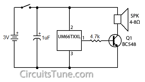 |
| Fig: Circuit Diagram of Song-Music generator using IC-UM66 |
UM66TXX series IC generate different songs-music, the song-music depends on the model of UM66TXX series IC’s. The song-music are listed below with model number.
UM66TXX Songs List:
UM66T01 = Jingle Bells + Santa Claus is coming to town + Wish you a Merry Xmas
UM66T02 = Jingle Bells
UM66T04 = Jingle Bells + Rudolph, the red-nosed reindeer + Joy the world
UM66T05 = Home sweet home
UM66T06 = Let me call you sweetheart
UM66T08 = Happy birthday to you
UM66T09 = Wedding march
UM66T11 = Love me tender, Love me true
UM66T13 = Easter parade
UM66T19 = For Elise
UM66T32 = Waltz
UM66T33 = Mary had a little lamb
UM66T34 = The train is running fast
UM66T68 = Its small world
Wednesday, December 18, 2013
Easy Loudspeaker Circuit For Telephone
This below circuit is a easy hands-free telephone receiver system. This doesn’t have dialing circuit so, it’s not a total phone replacement circuit, but it’s just only a loudspeaker system (i.e, phone receiver,not dialer). This is a easy circuit with all parts easily available, and without any complex I.C. It is made of just capacitors, diodes, resistors, and transistors. This circuit can be made within 70 rupees and it compromises of the following sections,

Read the rest entry[...]
- Power rectifier and filter section
This section is made of a simple bridge rectifier and a indicating power LED. - Voltage regulator section
This section is made upon transistor Sl100, which is a general purpose NPN transistor in metal package. That is used to regulate voltage at a level of 9+0.6=9.6V by a 9V zener diode. - Speaker output section
This section contains a high impedance speaker and two BC548 NPN transistor to amplify the signal from line, the input of the 548 transistor pair is fed with a linear or pot control of 10K for volume adjust. - Microphone input section
This section contains a condenser microphone (tablet) and two BC548 NPN transistor to amplify the signal from mic, the output of the 548 transistor pair is fed with a linear or pot control of 10K for volume adjust to the line.
Tuesday, December 17, 2013
Build a Power supply Protection Circuit Diagram
Why Build a Power supply Protection Circuit Diagram. When using a regulated supply to reduce a supply voltage there is always the danger of component failure in the supply and consequent damage to the equipment. A fuse will protect when excess current is drawn, but might be too slow to cope with over voltage conditions. The values shown are for a 12 V supply being dropped to 5 V.
Power supply Protection Circuit Diagram

The trip voltage is set to 5.7 V to protect the equipment in the event of a regulator fault. The 330 ohm resistor and the 500 ohm potentiometer form a potential divider which samples the output voltage as set by adjustment of the potentiometer. The SCR is selected to carry at least twice the fuse rating. The full supply voltage is connected to the input of the regulator.
The 2N2906 is held bias off by the 10 k resistor and the SCR so that the LED is held off. If the output voltage rises above a set trip value then the SCR will conduct, the fuse will blow, and the 2N3906 will be supplied with base current via the 10 k resistor, and the LED will light up.
Subscribe to:
Posts (Atom)